4D Facial Dynamics
Facial 3D analyses has been a big development target by the science community. This feeds a great variety of purposes like security, entertainment, psychology, and mostly face facial expression recognition. The face's dynamics is a inherent characteristic of each people, thus, this can be a great leverage over the 2D study than can be explored. Furthermore, the 3D models allow to eliminate some variables, such as the pose and lighting, to subsequent studies.
There is a wide variety of facial 2D databases, competing with a smaller number of 3D data, however, at present, there are very few dynamic 3D or 4D model databases, with time being the fourth dimension. This has been a motivation for developing a 4D high resolution reconstruction platform for building a database of 9 different sequences of 65 persons, 7 of them with 4 repetitions per expression, totalling 774 expressions and 38700 3D models.
4D Facial Database
System setup
Two stereo pairs were used on the flanks of the subject at about 30o. These cameras were mounted on a frame with a monitor that also serve as a guide to obtain the expressions. The optics used were the Fujinon 1:1.4 9mm maximizing the subject's face in the 1024x768 pixels of the camera Point Grey FL2 Flea2-08S2M/C. A stereo baseline of about 9 cm was chosen which allows us to obtain good precision and at the same time makes stereo correspondence much easier and also minimize occlusion. A light diffuser projector facing the subject was in charge of lighting the face's front. Complementing these, four identical projectors at about 45o and 135o of the subject illuminates the whole surface evenly. All this is within a 2 meters sided cube with blank diffuser coated fabric minimizing the shadows on the inside. A chess-like board was used for system calibration based on Bouguet and Zhang methods. A machine with an Intel Core i7 950 processor acquires images of the four synchronized cameras with full resolution at a frame rate of 20 frames per second. Each stereo pair returns a color image (top camera) together with a gray level image (bottom camera), this way, the color image can be used to obtain the texture of the model and at the same time, to provide depth or disparity images with their stereo pair after converted to graylevel image. All images are previously rectified according to calibration parameters before being stored in the database.
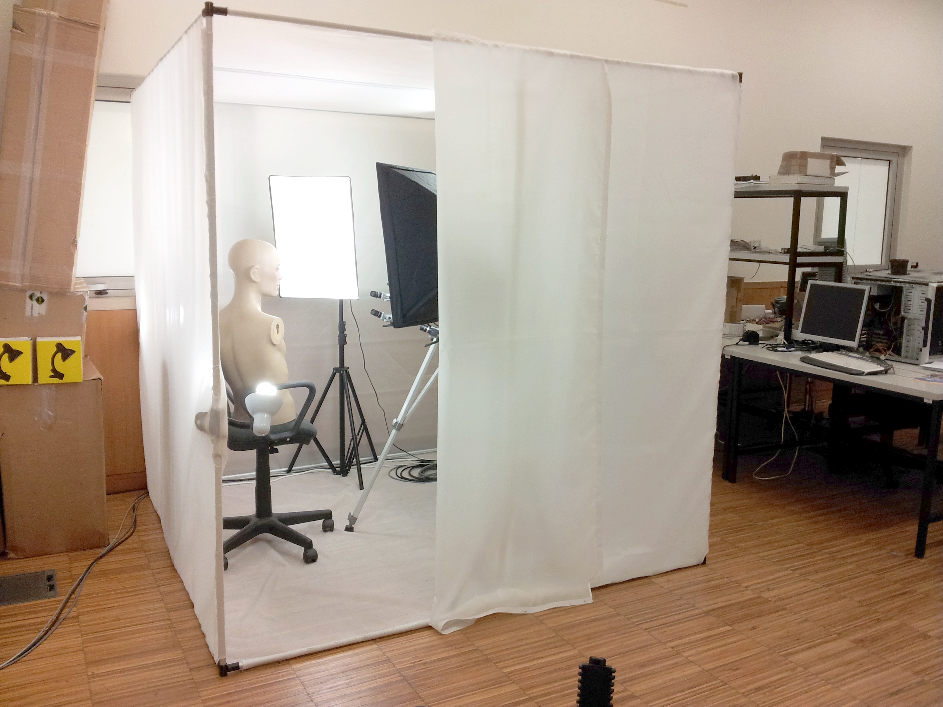
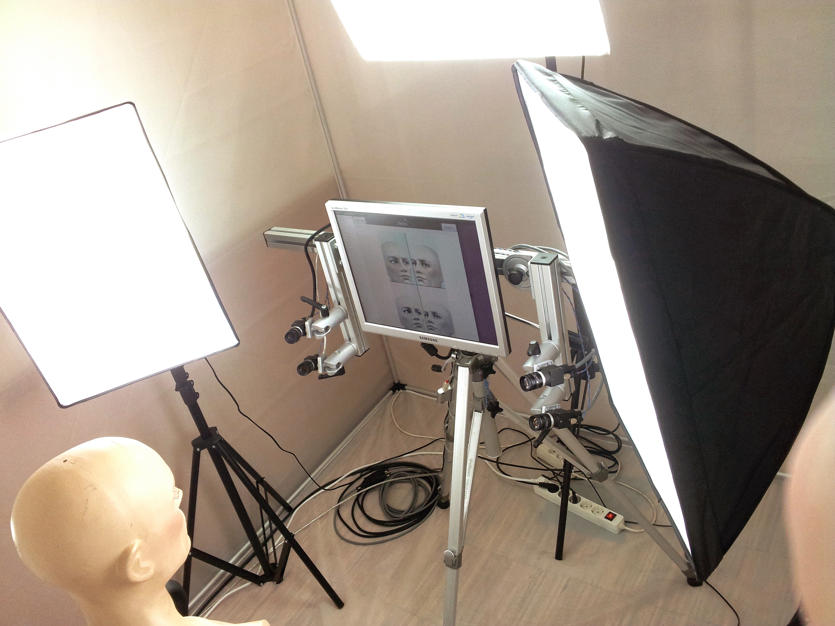
Figure 1: System setup
Capture protocol
Each participant was instructed to pose at about 60 cm in front of the monitor. For each individual 9 sequences were recorded: angry, contempt, disgust, fear, happy, sad, surprise and neutral, adding the phrase "yes we can". Each sequence starts with a neutral expression (relaxed) followed progressively to the expression peak and going back to neutral with approximately 4 seconds long. The sample universe contains 65 participants, 14 of whom were female. Of all 7 realized 4 repetitions per expression. Repetitions are a very important and useful data since it allows to train and test algorithms with different data of the same person. This kind of data is very rare to find out there, even 2D/3D, making this database very unique. A graphical user interface helped the participants to implement the expressions as described by the facial action coding system (FACS). This tells us that each expression can be decomposed into small facial components called Action Units (AUs), with this we can characterize, for example, the expression of sadness with three independent movements: Inner Brow Raiser Lowerer + Brow + Lip Corner Depressor .
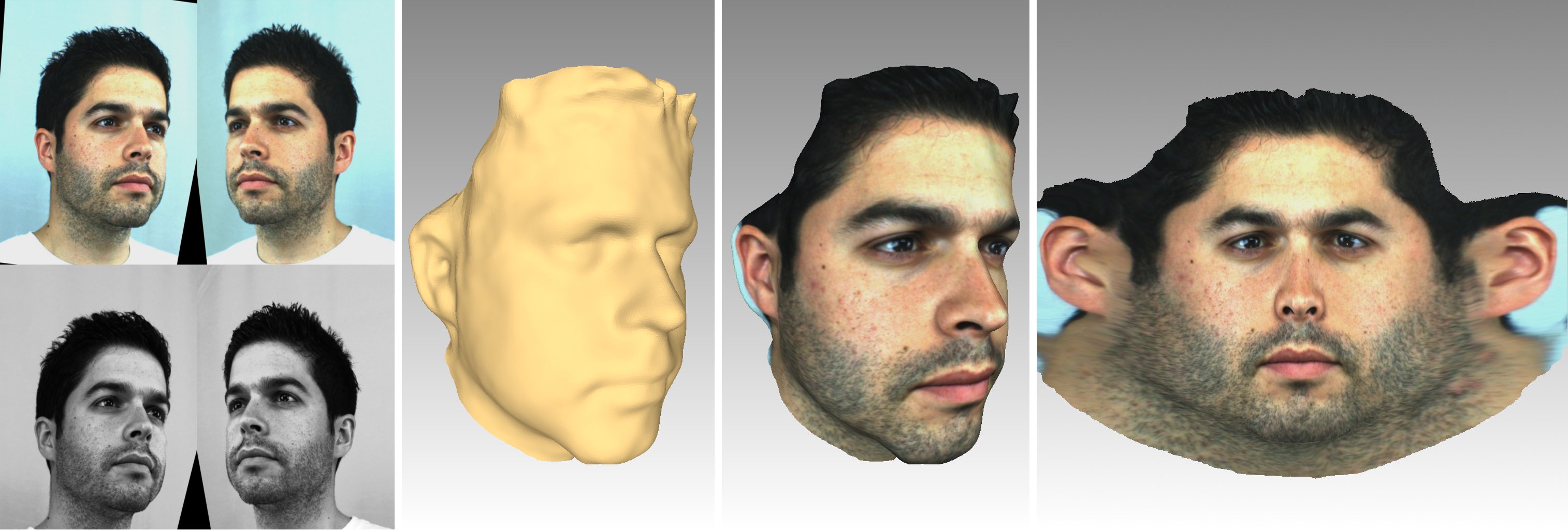
Figure 2: Rectified images at left, 3D model at center and the correspondent cylindrical projection at right
Data organization
The database is structured by individuals. From each one derive 9 blocks with different expressions. Each block contains a sequence of rectified images along with it respective video, the sequence of 3D models in VRML format, a sequence of images of the cylindrical texture projection along with the respective video and a sequence of 3D registered model in VRML format along with a registered 2D (pixel) and 3D(indexed to original 3D model) files. Each 3D model contains about 53,000 vertices. In total, 65 participants provide us with 774 expressions which leads this database to about 663 GigaBytes. A visualization tool was developed to allows the observation of all available data in several ways: point cloud, mesh, surface, texture, form either original or registered model from any point of view.
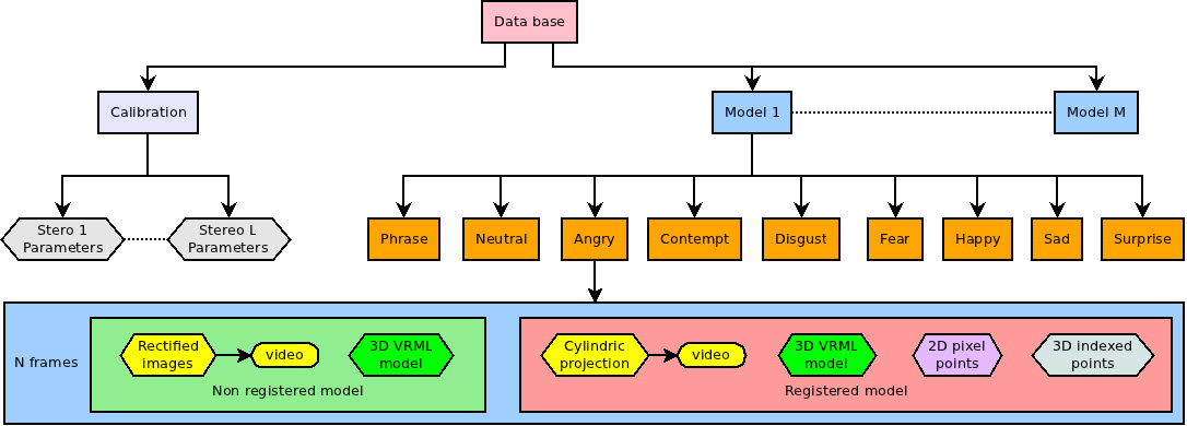
Figure 3: Data organization
High-resolution 3D reconstruction
A high resolution 3D reconstruction platform has been developed for the creation of the database. This chapter will explain the choices made and the most important methods used.
Narrow baseline
A system was developed for high quality 3D reconstruction based on two stereo pairs in order to cover a larger field of view. This enables the subject to have more movement freedom but if the goal was to obtain the complete head it could have been added more stereo pairs straight way. The stereo baseline is the distance between their focus points, which is a very important factor in these systems. A long baseline gives more accurate results but it makes the establishment of correspondences between cameras harder and at the same time increases the risk of occlusions. On the other hand, a short baseline makes feature matching much simpler but lowers the accuracy. Since the choice of the optimal value will depend much on the distance of the cameras to the area of interest and the lenses focal length, we found the value of approximately 9 cm the best compromise. It is further noted that the cameras are not parallel, since the intersection of the lines takes place approximately in the background, thereby optimizing the common visible area among them.
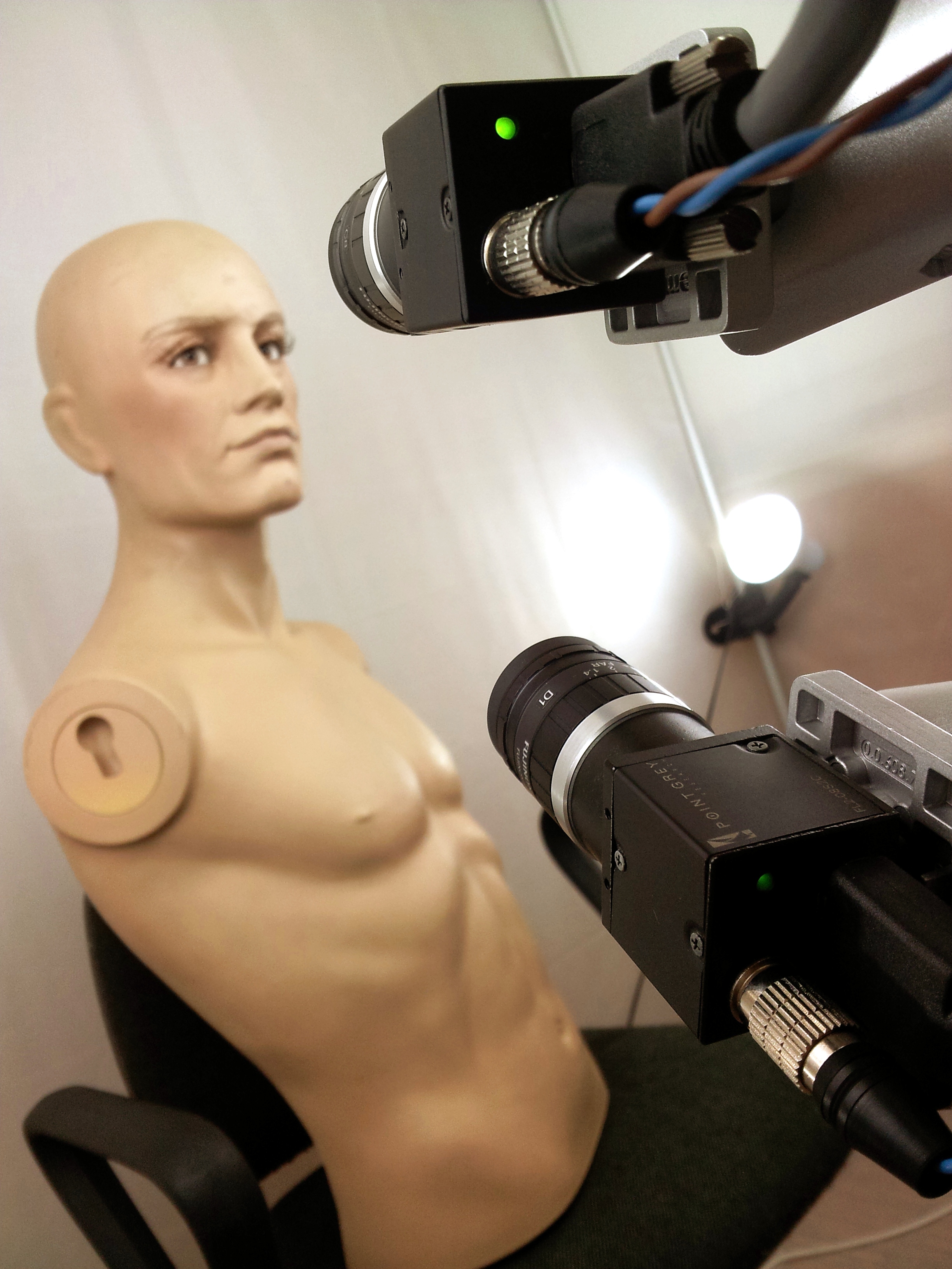
Figure 4: Photo of a stereo set
Passive stereore construction
In order to obtain a 3D point of a stereo pair the projection of this point in both cameras must be found and the algorithm LibELAS Library for Efficient Large-Scale Stereo Matching developed by the Karlsruhe Institute of Technology is in charge of this correspondence search. This algorithm provides a picture of depth, more technically, the disparity from a rectified stereo. The image rectification is necessary to reduce the search to one dimension allowing the corresponding point to be found in the same row of the other image. The disparity is the distance, in pixels, between the corresponding points in each image. This information together with the calibration parameters allows to generate the 3D point cloud, so each stereo pair provides a 3D point cloud with 1024x768 at best. The segmentation of the face is then made removing the background being simplified by deleting the farthest points from the central cloud, which represents the person's face.
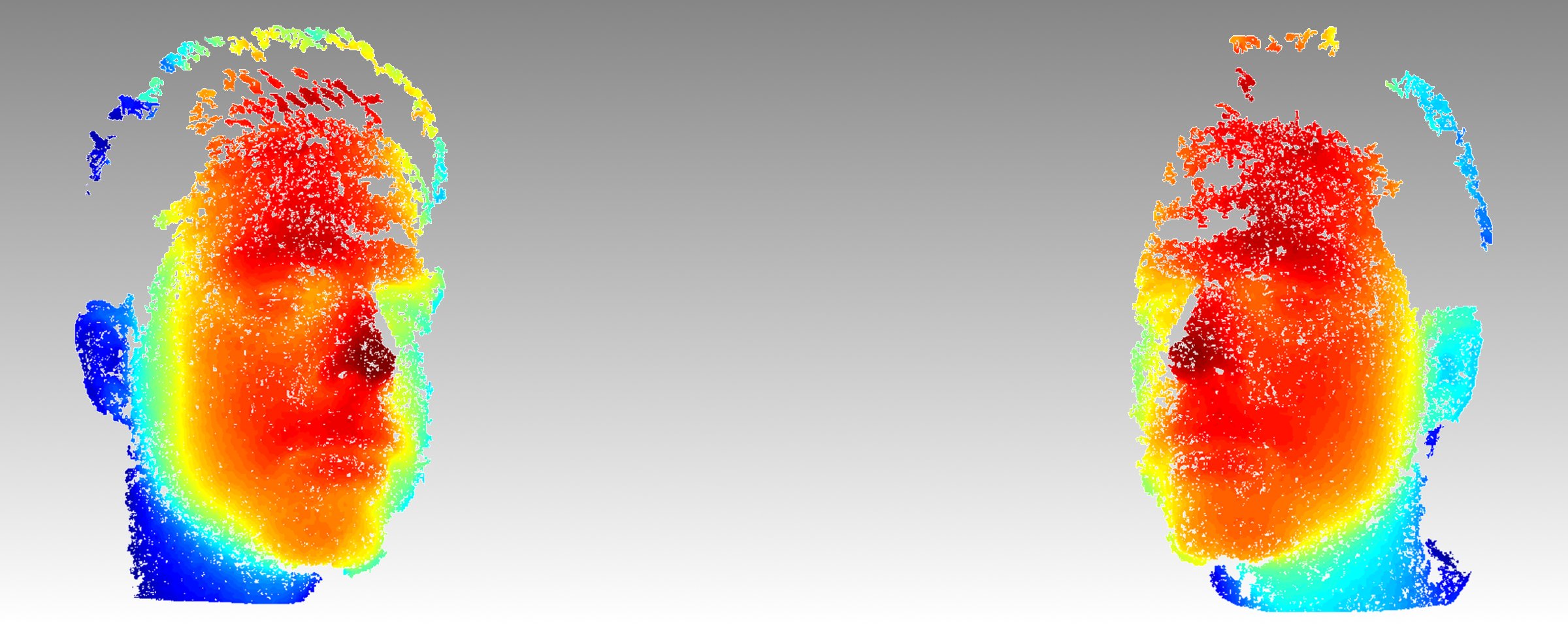
Figure 5: Disparities from the left and right stereo respectively
Align and merge point clouds
The next step is to find the best way to merge the two point clouds. The calibration parameters already provides fairly precisely the necessary transformation to refer all points in one frame, since each has its own reference. This transformation itself already merge the point clouds quite well, however, this coupling can be improved by running the ICP algorithm or Iterative Closest Point. This iterative algorithm finds matching pairs between clouds and creates a rigid body transformation that minimizes the distance between them until convergence.
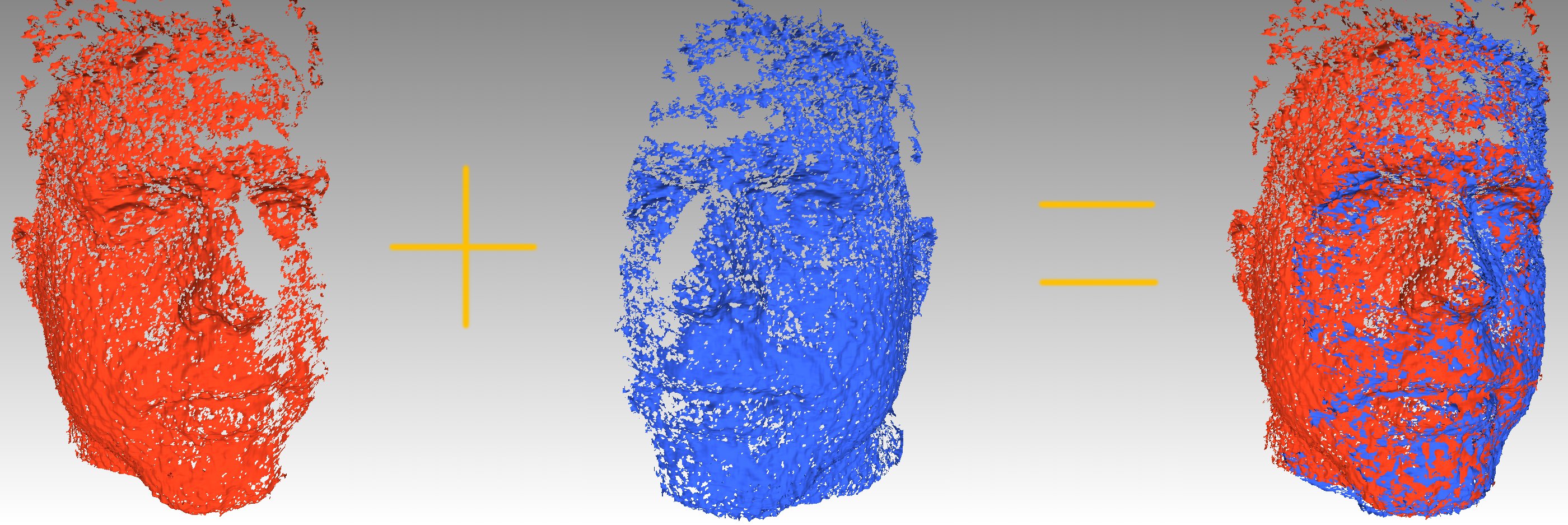 
Figure 6: Merging two point clouds
Poisson Surface reconstruction
At this time a point cloud was generated with variable point concentrations due to the clouds overlap. To create a homogeneous surface without holes was used the Poisson Surface Reconstruction algorithm developed by the Johns Hopkins University. Some features of this algorithm make it particularly suitable for this purpose, operating from a point cloud and delivering a closed surface without holes. Tuning their parameters controls the degree of fidelity to the surface's original points allowing to filter out some noise and also saving processing time. The amount of information required to represent the 3D model can be reduced approximating the surface to a mesh formed of triangular polygons as illustrated below.
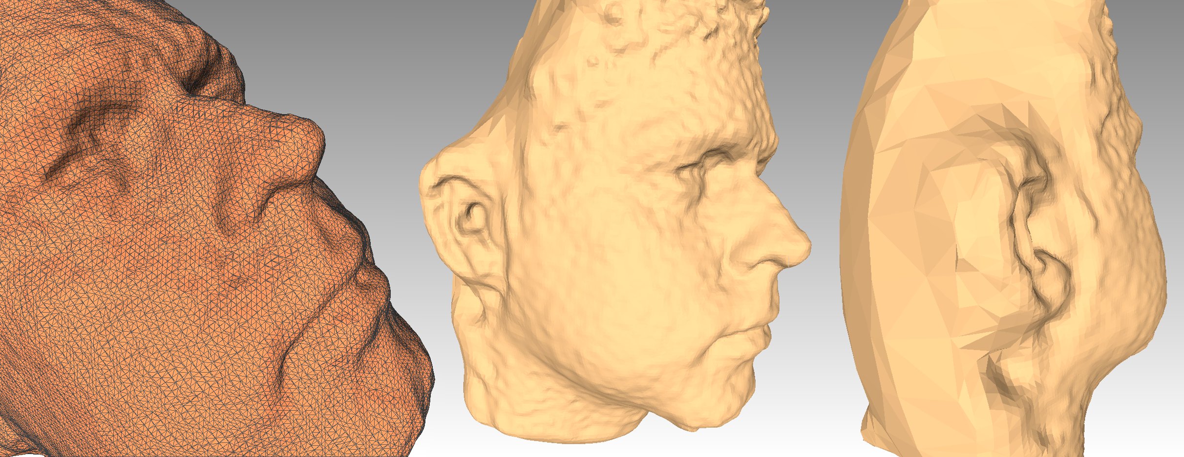
Figure 7: Poisson surface reconstruction sample
Face alignment
Since the subject's face is the only desired part, it's necessary to remove the back surface region. To do this was used a pre-generated mask for each subject containing only the desired surface. This mask is centered at a fixed coordinate system common to all participants. The 3D model is then fitted to this mask through ICP and the non-overlapping areas are removed. This makes all the faces aligned in a common static framework, which will prove essential to all of the following and later this transformation will revert to its original position.
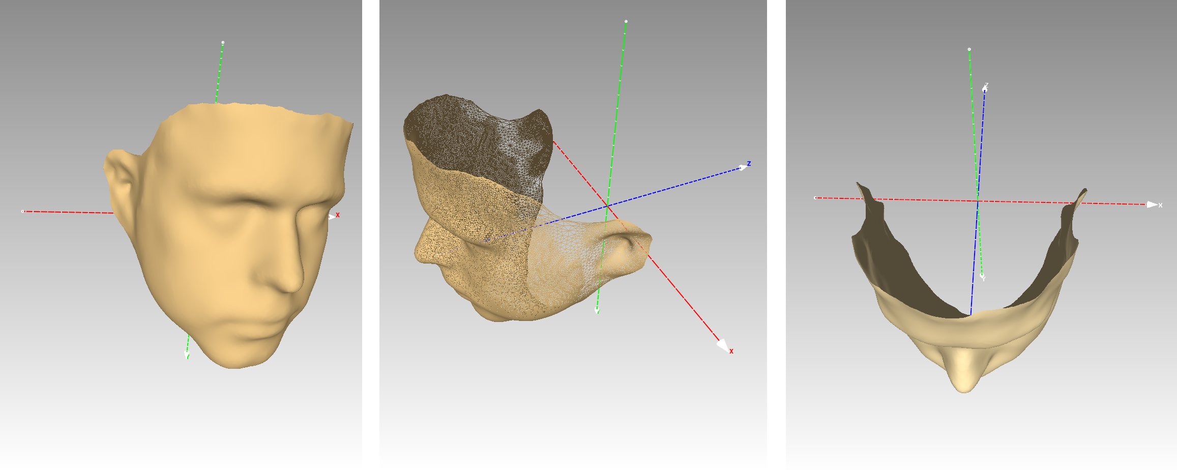 
Figure 8: Pre-generated mask
Texturization
So far the surface generation of the face was almost completed. For a higher level of realism the next phase of texture mapping on the surface of the model is required. This technique consists to assign short texture excerpts from the color cameras to all surface polygons of the 3D model. To do this, are used two different coordinate systems, with the 3D model being governed by (x, y, z) coordinates and the texture space represented by (u, v) coordinates at image plane level.
Texture coordinate generation
It's necessary to establish a link between all 3D model points and texture images. Since at this time there is no connection between them, all 3D points are projected to the camera planes so that each 3D (x, y, z) point has an associated (u, v) point on each image texture.
Optimal texture source selection
Now is important to decide which is the best view for each region. When there is only one texture source this task is quite simple, since the projection of the 3D model to the plane of the camera is sufficient to provide the necessary mapping coordinates. In this case there is more than one view of the subject so is necessary to decide which one could provide the optimum texture for each surface in order to maximize the resolution of the polygons and prevent occlusions that can occur when a region is visible only by one side. To this a multiple decision criteria can be used. One of the most commonly used is to choose a source that provides the largest projected area of the triangle in the images, thereby maximizing the resolution. However, there may be small pieces that although verifying this criterion may be closer to one camera than the other, which may contain low quality due to the greater distance. Taking this into account there also could be added a factor that favors the shortest distance between the polygons center and cameras. Finally, since the face is centered, a third factor could be added seeking to divide the face into two parts (left and right) directing these to the nearest camera. This last criterion is the simplest to put into practice, and adapts perfectly to human faces so this is the more weightier factor in the decision. Sometimes there are certain areas, that due to the Poisson reconstruction process may not be visible from any camera like the area below the chin, and in this case, the last criteria takes full control, having the effect of the allocation of a neighboring texture. However since this is an approximation there may be aberrations in these areas, as shown by the following figure at right. Finally all the not referenced (u, v) coordinates are eliminated.
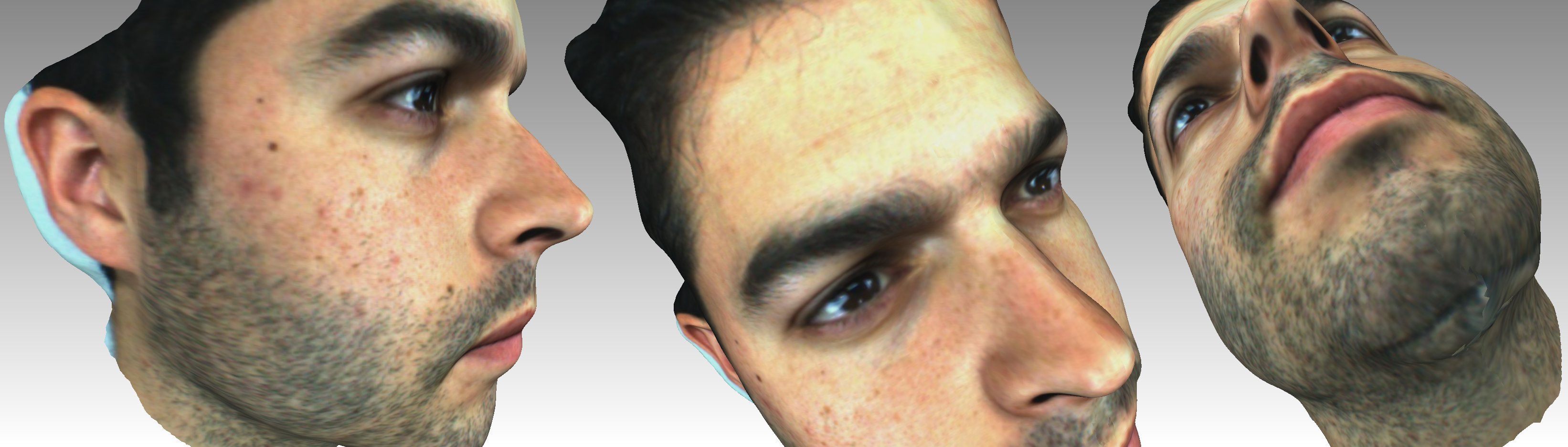 
Figure 9: At left and center the distortions caused by the multiple texture sources are almost imperceptible. On the right it can be seen that the area under the chin contains some aberrations due to not being visible to any of the cameras.
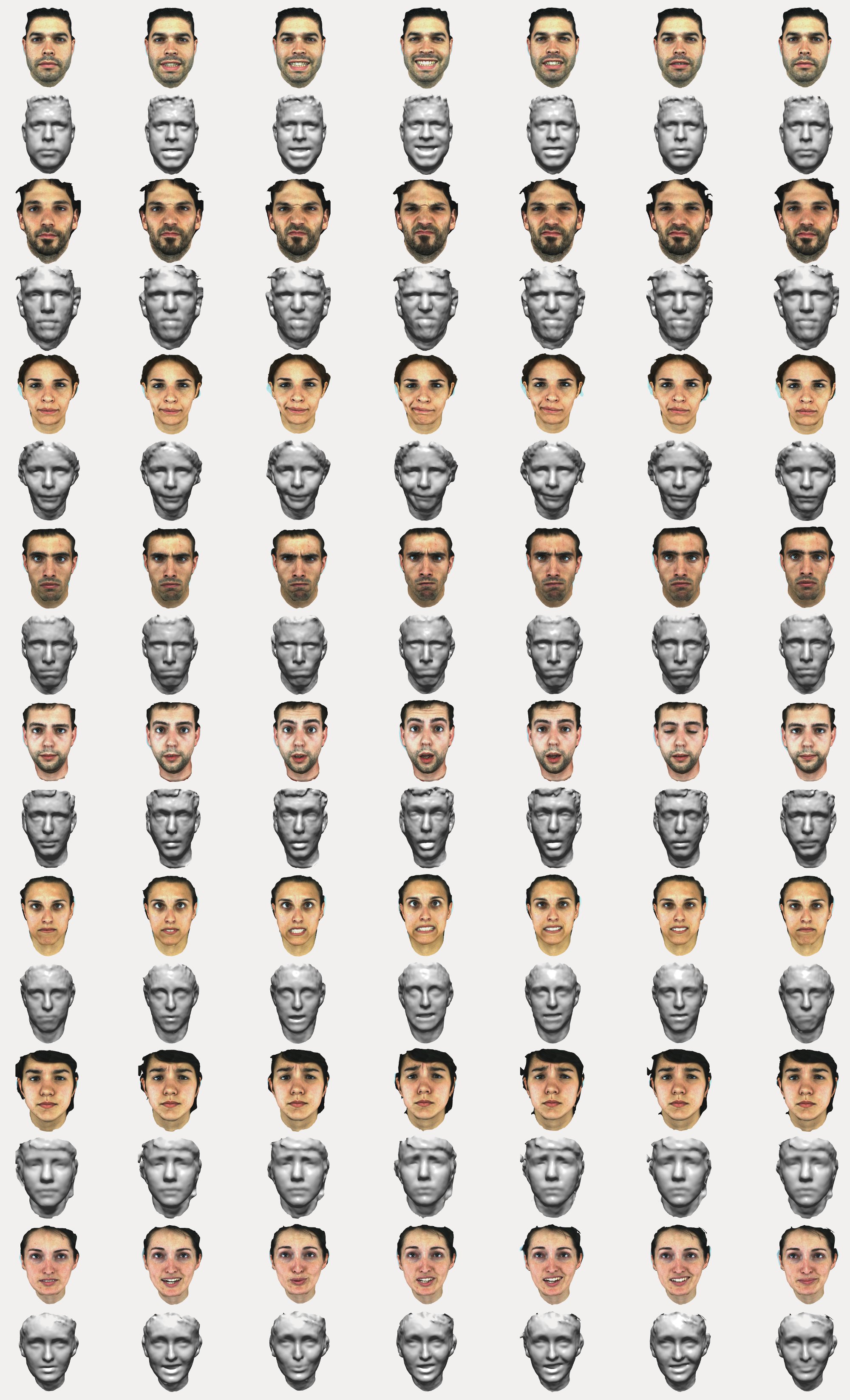 
Figure 10: 3D model samples. From top to bottom: Happy, Disgust, Contempt, Angry, Surprise, Fear, Sad and Phrase.
Registration of facial features
Given that this is a dynamic facial model database, i.e. sequences of 3D models over time, is extremely useful to analyse the variation of a consistent set of points in space and time. As the model created so far lacks of a constant number of points and there is no correlation between the order of points or match points between consecutive frames in time, we developed a step combining the AAM (Active Appearance Model) with the TPS (Thin Plate Splines) algorithms in order to track a certain number of face features over time. However, this AAM is not built from the typical front camera images since these models cannot be fully viewed from one point of view. So a virtual image of the 3D model was created in which the surface is mapped by a cylindrical projection (θ, h, ρ) to the reference of the pre-generated mask and then converting (θ, h) for the image plane (u, v) jeopardizing the ρ, resulting in the image seen in the figure below.
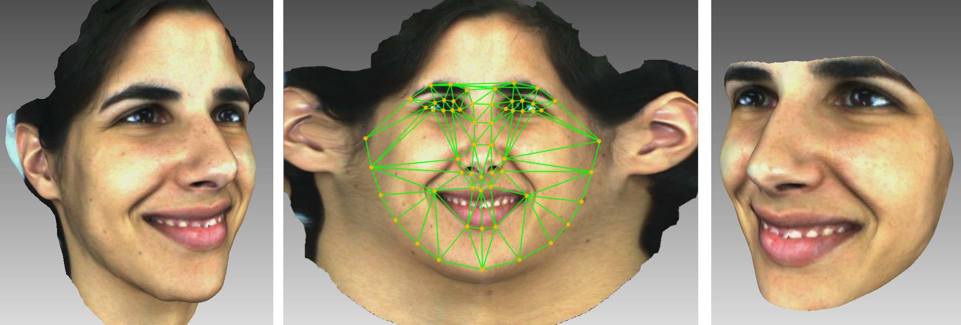
Figure 11: Face features tracking
This AAM is defined by 58 points Pi to be fitted to each frame throughout the sequence. Lets call Pprior the sparse 58 points from the average of all trained faces and Dprior the dense set of points contained in the convex hull of Pprior. Since this AAM runs with 1024 x 1024 pixel images, Dprior will be a dense set of about 48000 constant points through the whole database. To each frame i, TPS will compare Pi with Pprior providing us a function that defines the deformation between this two sets in the image space. This function will be used to map Dprior to each frame originating Di. The deformation between Di and Dprior will be a dense replica of the sparse Pi and Pprior relation. This way we can achieve a dense face registration with a constant and persistent set of points through the whole sequence. At last, these points are re-projected to 3D space calculating the intersection point of the line (θ, h, ρ = 1) with the surface of the 3D model and storing the closest 3D point. From these projection are also extracted the texture coordinates generating a fine textured mesh to be stored in VRML format along with Di pixel points and 3D indexed files.
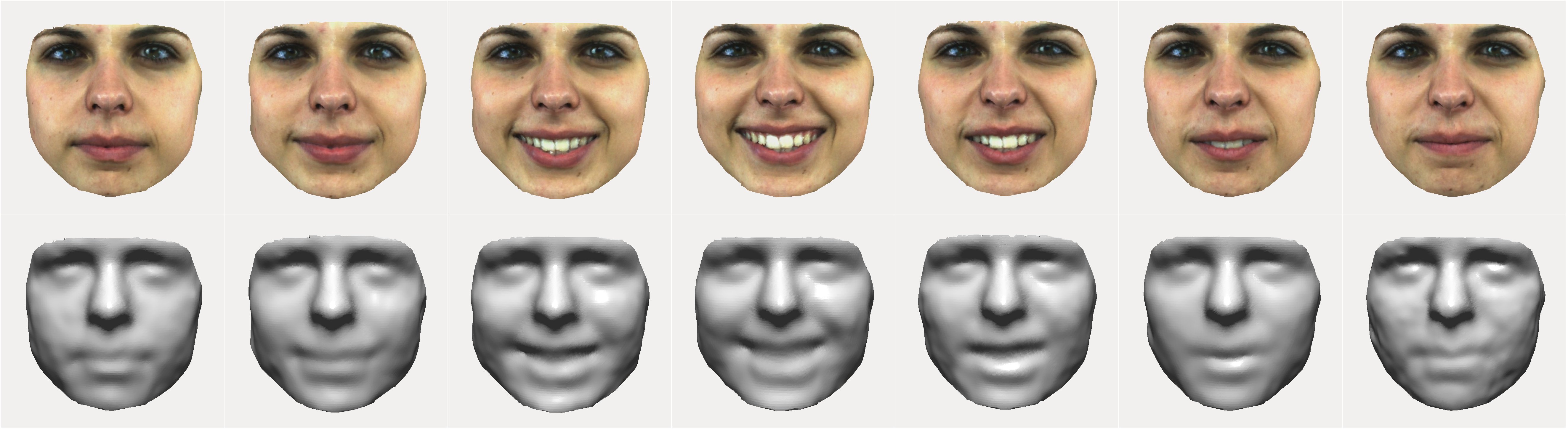
Figure 12: Samples of temporal tracking


DEMOS

Demonstration videos